
10-Bit Video for Archival Digitization: SNR and Bit Depth for Analog Video Capture (Part 1)
SNR and Bit Depth for Analog Video Capture
This is part one of a two-part series. This post covers the fundamentals of bit depth, noise, and signal-to-noise ratio as they apply to archival video digitization. Part 2 covers measured SNR values for common tape formats and the practical case for 10-bit capture.
What Archival Digitization Is Trying to Preserve
Archival digitization is a little like taking a “freeze-frame” of a fragile object before time (or a chewed tape path) takes it away. The goal isn’t to make old footage look modern. It’s to preserve the signal that exists on the tape, including the imperfections that tell you what the tape really contained at the moment of playback.
A high-quality archival master must faithfully reflect the original tape output, avoid irreversible decisions such as “baking in” aggressive noise reduction, and remain suitable for future reprocessing with improved tools and techniques. While a “pretty” access or mezzanine copy can be created later, the primary goal of the archival master is accuracy and fidelity, not aesthetic enhancement.
Why Noise Is Part of the Historical Record
Analog formats carry noise: tape grain, chroma crawl, dropout, hum, head switching artifacts, and all the tiny irregularities that come with magnetic recording. Some of that noise is unavoidable, and some of it is diagnostic.

On a videotape, noise isn’t a “layer” that you are trying to avoid. Noise is part of the signal. The details in the image, like hair or other fine textures, aren’t sitting cleanly on top of noise. Rather, they gradually fall off into the noise. There is no clear boundary where the signal “ends” and the noise “starts.”
Tape noise can also serve as a source of information about the original. It can help you deduce whether the tape is an original or a copy, whether the binder is shedding, or whether the deck playing the tape is having issues. For all of these reasons, the archival master should preserve the noise faithfully, not discard it.
Noise and Signal-to-Noise Ratio
Before we talk about bit depth, it helps to first understand what noise is and how we measure it, because the whole point of choosing the right bit depth is to avoid adding more noise than the tape already has.
What Is Noise?
Noise is the amount an analog signal varies from its intended value. Imagine we gave a VCR a video signal that is exactly 100.00 mV and recorded that onto a tape. When we play that tape back, the signal will be close to 100.00 mV, but it won’t be exact. Flaws in the machine and the tape itself cause the voltage to deviate. For instance, the wires inside the VCR are not perfectly pure copper, and impurities cause small voltage drops. Other real-world factors impact the signal too. The changes aren’t large, but they aren’t zero. If we play our recorded tape back, we might get a value that bounces around between, say, 98.5 mV and 101.5 mV.
That variation is the noise.
Every link in the signal chain has its own noise floor, the total, average amount of noise that is always present. For digitizing a videotape, the relevant noise floor is the one present when the deck is playing a solid black recording. The solid black video serves as our “no signal” condition. We need the tape actually playing this “empty” signal (as opposed to generating it externally) because the tape itself is a source of noise. Any voltage deviation from a perfect black signal is the analog noise floor.
Signal-to-Noise Ratio (SNR)
Signal-to-noise ratio is exactly what it sounds like: the ratio between the signal voltage and the noise voltage. This is typically measured in decibels. The standard formula for the SNR of voltages (such as video) is:
Where Vs is the signal strength in volts and Vn is the noise strength in volts.
A higher SNR means a cleaner signal with less noise relative to the picture content. A low SNR means the noise is a larger proportion of the total signal. We’ll come back to specific SNR numbers for various tape formats in Part 2. For now, the key takeaway is that every tape format has a characteristic SNR range, and that number sets a ceiling on what any digitization can capture.
Bit Depth Basics
Now we can tackle the core question: how finely should a digitizer represent the signal from the tape?
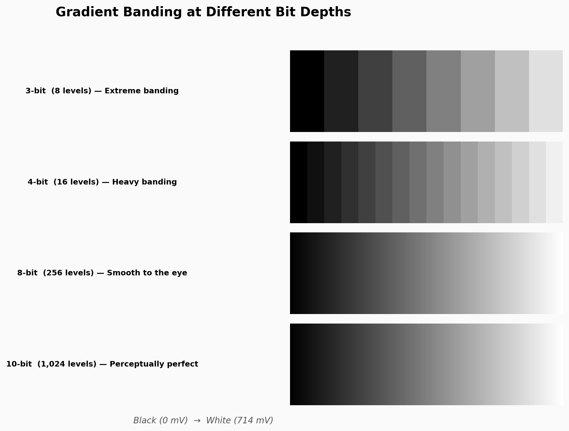
Analog video doesn’t exist in the world of clean numbers. The signal is just variations in voltage. In a standard NTSC video signal, this voltage can be any value between −286 mV and 714 mV (a total range of exactly 1000 mV). There is no limit on the number of digits after the decimal point.
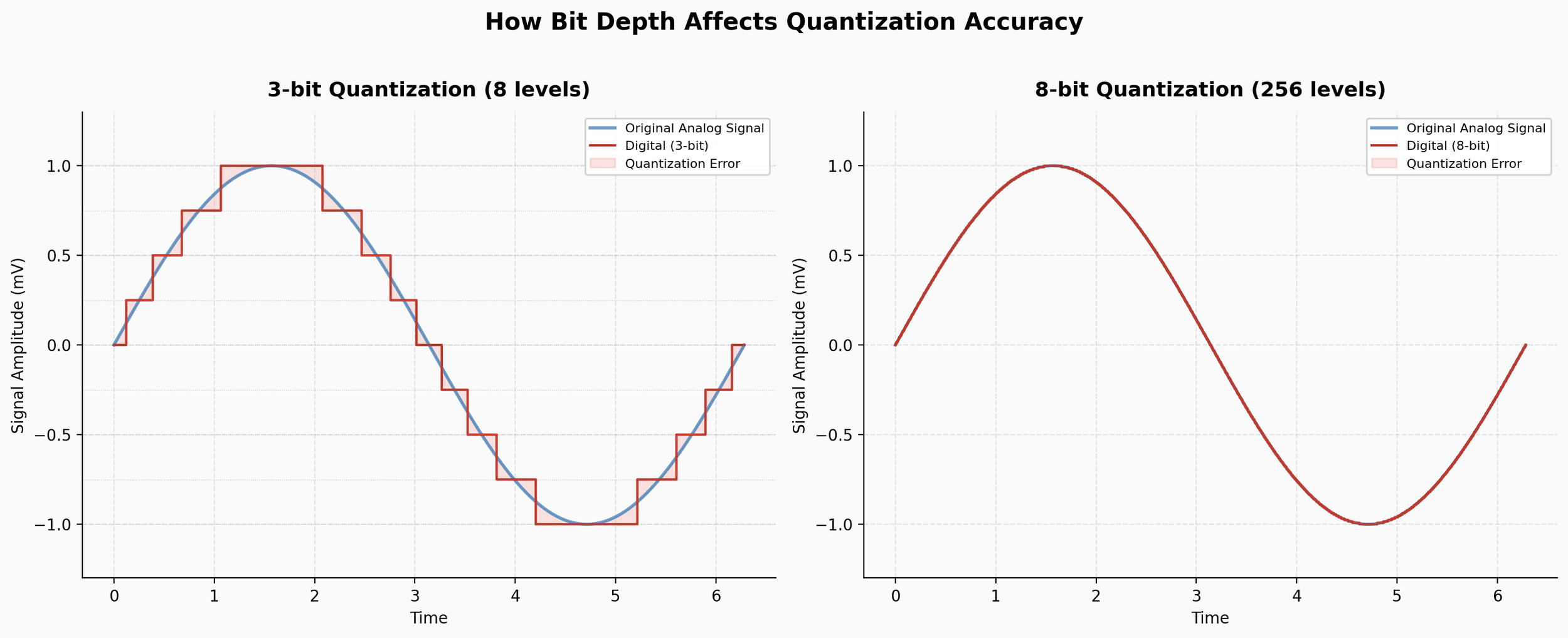
Bit depth is the number of discrete steps these voltage values are rounded to so the computer can work with them. More steps means a more accurate digital representation of the original analog signal. Fewer steps means more rounding error.
Here’s a simple example. If we have 1,000 steps for our 1,000 mV range, voltages would be rounded to the nearest millivolt. If we only have 100 steps, values would be rounded to the nearest 10 mV:
| Real-World Voltage | Computer Value (100 steps) | Computer Value (1,000 steps) |
|---|---|---|
| 47.248739… mV | 50 mV | 47 mV |
| 645.16493… mV | 650 mV | 645 mV |
| 234.96535… mV | 230 mV | 235 mV |
| 340.23312… mV | 340 mV | 340 mV |
Sometimes the rounded value is very close to the real one. Sometimes it’s off by several millivolts. More steps is desirable because it more accurately represents the original signal coming off the tape.
Standard Bit Depths
We call this rounding process quantization. The number of steps is measured in bits, which is the total number of 1’s and 0’s the computer can use to define a value. One bit gives you 2 steps (0 or 1). Two bits gives you four steps (00, 01, 10, 11). Each additional bit doubles the number of available steps. I was using 100 and 1,000 steps for an easy example above, but the standard values are:
| Bits | Steps | Usage |
|---|---|---|
| 1-bit | 2 | Rarely used outside computer science |
| 4-bit | 16 | Historical; early computers |
| 6-bit | 64 | Historical; early computers |
| 8-bit | 256 | Extremely common |
| 10-bit | 1,024 | Common, and gaining popularity |
| 12-bit | 4,096 | Common in modern cinema cameras |
| 16-bit | 65,536 | Infrequent; high-end film and photography |
Why not always use the largest number of bits possible? Because adding bits increases file size and the complexity of the equipment needed to work with the video. Adding bits means there is simply more data to deal with. The goal is to have enough bits that we know we are preserving everything, but not more than we need.
Channels and Color
Before quantizing the image into discrete steps, the signal is first split into three components. Usually these are a black-and-white image (called Luma, abbreviated Y) and two color-difference signals (called Chroma, abbreviated Cb and Cr). Each component is called a channel, and together this system is known as YCbCr.
(Note: The abbreviations YPbPr and YUV are often used interchangeably with YCbCr. Technically they refer to different things, but in casual usage you’ll see them swapped freely.)
Each channel is quantized independently using the bit-depth system described above. This means that an 8-bit black-and-white image has 256 possible shades of gray (one channel), but an 8-bit color video has 256 × 256 × 256 = 16,777,216 possible colors (one set of 256 for each channel).
To make matters more confusing, sometimes people add the bits from all three channels together. So they might call 8-bit color video “24-bit” (8 × 3 = 24). In my experience, people who work in film and video tend to use the “bits per channel” convention, while people in photography or graphics use the “total bits” system. To avoid confusion, I’ll use the unit bpc (bits per channel) throughout this post and its sequel.
Quantization Noise: The Extra Noise You Don’t Want
When analog video is converted to digital, the capture card must round the continuous signal to discrete values. That rounding error is quantization noise, and it’s a second noise source layered on top of the analog tape’s own inherent noise.
Each form of noise has its own noise floor. The analog noise floor comes from the tape and the playback electronics, as we discussed above. The quantization noise floor comes from the rounding process itself.
Here’s why the rounding creates a fluctuating error: 500.1 mV and 500.4 mV will each be rounded to 500 mV, even though 500.4 mV is further from the rounded value. The magnitude of the rounding error varies with every sample. That variation is, itself, a form of noise.
Quantization SNR
We can calculate the signal-to-noise ratio of the quantization process itself. For a perfect converter, the formula is:
Where n is the number of bits. Note that this is the theoretical maximum for an ideal converter; real-world hardware may fall short. For exact numbers, you’d need the datasheet of the converter chip on your capture card. For simplicity, we’ll use the ideal numbers here and assume full-range video signals.
Here is our bit depth table again, this time with the quantization SNR added:
| Bits | Steps | Quantization SNR | Usage |
|---|---|---|---|
| 1-bit | 2 | 7.78 dB | Rarely used outside computer science |
| 4-bit | 16 | 25.84 dB | Historical; early computers |
| 6-bit | 64 | 37.88 dB | Historical; early computers |
| 8-bit | 256 | 49.92 dB | Extremely common |
| 10-bit | 1,024 | 61.96 dB | Common, and gaining popularity |
| 12-bit | 4,096 | 74.00 dB | Common in modern cinema cameras |
| 16-bit | 65,536 | 98.08 dB | Infrequent; high-end film and photography |
The Key Principle
This is the central concept: the quantization noise floor must be lower than the analog tape’s noise floor.
If there is more quantization noise than analog noise, the two sources compound. You will be making the video look worse than the original tape. However, if the quantization noise floor is lower than the analog noise floor, the quantization noise is effectively drowned out. The result is a more accurate capture where, ideally, all of the original analog signal is preserved, noise and all.
This is the question that bit depth answers, and it’s the question we’ll resolve with real-world data in Part 2. We’ll look at published SNR specifications from manufacturer service manuals for VHS, S-VHS, U-Matic, Betacam SP, 1-inch Type C, Video8, and Hi8, and compare those numbers to the quantization SNR table above to determine when 8-bit capture is sufficient and when 10-bit is necessary.